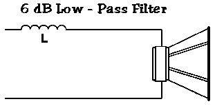
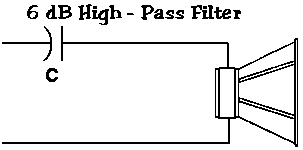
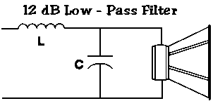
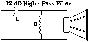
The easiest (and cheapest) crossovers to build are 6 dB/Oct, made of either an inductor or capacitor inline. While this might work as a simple fix, or at a crossover frequency that is not close to the speaker frequency response limits, it is not the best solution. For higher slope crossovers, complexity and cost add up quickly.
Parts of a Crossover Network
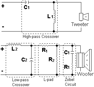
- Filter: This is the real crossover. It blocks undesired frequencies by increasing impedance seen by the amplifier. Made up of capacitors and inductors. There are three types: High pass, low pass and bandpass (high pass and low pass filters used together).
- L-pad: Attenuates the output of a speaker, while presenting a constant load to the amplifier. L-pads are made using two resistors that dissipate power that would go to the speaker. It is used to match “volume” levels of different speakers.
- Impedance Stabilization: Commonly known as a Zobel circuit. It uses a capacitor and resistor to compensate for the inductive effects of the speaker coil, making the speaker play in a more linear fashion. This also makes the amplifier see a more stable load (speaker impedance varies with frequency). Zobel networks are used on speakers that play lower frequencies, not tweeters.
How to Pick Crossover Components
Capacitors: If you can afford them, try to get Mylar or polypropylene capacitors, especially when they are used in series (high-pass filters). For low pass filters, or high capacitance values non-polarized electrolytic capacitors have to be used.
Inductors: Most critical in low-pass filters, when they are placed in series. For audiophile quality sound, CFAC (Copper-foil-air-core) inductors are probably the best choice, but at a high cost. Most cost/quality effective option is air core inductors for high-end crossovers. At larger inductance values, the series DC resistance in air core inductors becomes a problem. This is when iron core inductors would have to be used.
Resistors: High-power resistors are bulky. Always pick a higher wattage than you would need on average conditions. Get non-inductive resistors for best performance.
L-pads: There are commercially available variable L-pads, or a set can be fabricated using two high-power resistors. If you buy an L-pad, it is very important that you get the right value. I.e: For 4-ohm speakers, get a 4-ohm L-pad. A dual 8-ohm L-pad could be wired in parallel to operate with a single 4-ohm speaker, at twice power handling.
Circuit Boards: Chose double sided copper boards. The thicker the copper coating and insulating material, the better. You can either etch the board with chemicals, or with a Dremel® tool.
Crossover Design Tips
Capacitor voltage/power ratings: Typically, 50-volt capacitors can handle up to 70 RMS Watts, 100v can handle 200w and 250v up to 300w.
Inductors gauge/power ratings: In inductors, the gauge of the wire used determines power handling. Common values are: 20 gauge = 180 watts, 18ga = 250 to 300w, 16ga = 500w and 14ga = 800w.
Series/parallel inductors add up in the same way as resistors, capacitors add up in the opposite way (capacitance increases in parallel, decreases in series). For formulas, look at the “speaker/sub wiring” page.
In crossovers with large non-polarized electrolytic caps, sound quality can be improved by bypassing them with a small value (0.01 to 0.47 µF) film or foil polypropylene capacitor in parallel (tip courtesy of Parts Express).
Crossover Initial Design
Plan very carefully which frequency you are using for the crossover. Once you buy the components, you can’t change it. Consider car’s response, speaker’s response, slope, acoustical effects, etc.
Whether it is plugging numbers into formulas, or having a computer figure out the values, you will come up with a set of inductor and capacitor values. Most likely, the values you have are not commercially available. You will have to play around with frequencies and commercially available values to compromise on a good design without much deviation from theoretical data.
Once you have your values figured out, you need to calculate power. Always over-engineer crossovers and pick your inductor’s wire gauge and capacitor’s max. voltage accordingly. Any weak component will cause problems in the overall crossover design.
If you have the resources, try to run a simulation of the crossover’s interaction with the speakers parameters, see what comes up and how shifts in voltage and current will affect the response.
Building The PCB
Take your time figuring out the best component layout possible. A good layout takes up a least amount of space while avoiding traces to cross each other. Two sided-copper boards are easier to work with. If there is no way to avoid traces crossing, both sides can be used to keep from soldering jumper wires.
Once you have a tentative layout and have analyzed that the layout matches the schematics, draw each component’s outline with a pencil. Mark where component leads and input/output wires need to be drilled in the board. Drill all component holes and test fit all the components without soldering. Etch or grind away parts of the board to create traces. If there is a possibility of a component shorting out traces, etch an outline around the component to avoid problems.
It is good practice to glue or wire tie (or both) components to the board. This way, rattles and vibrations that can stress and break wire leads are minimized. Take one component at a time, glue it to the board (hot melt glue works great), and then solder the leads. Cut excess wire. Repeat the process for all the components and wires.
Testing
First, visually trace all the connections and junctions on both sides of the board. Make sure there are no short/open circuits.
The second step is to test the board. Check the board to make sure there are no DC short circuits. Connect the board to an amplifier and speaker. You can either use an RTA or test tones to determine the board’s frequency response. Use a volume level a bit higher than the background noise in your test environment. If the frequency response (crossover point and slope) do not match theoretical data, you might have a short or loose connection. Re-inspect your circuit.
Quick Parts Reference
|
Guidelines For 6-dB/Octave Crossovers |
||||||
|
|
||||||
|
|
||||||
| Frequency | 2 ohms | 4 ohms | 8 ohms | |||
|---|---|---|---|---|---|---|
| (Hertz) | L | C | L | C | L | C |
| 80 | 4.1 mH | 1000 µF | 8.2 mH | 500 µF | 16 mH | 250 µF |
| 100 | 3.1 mH | 800 µF | 6.2 mH | 400 µF | 12 mH | 200 µF |
| 130 | 2.4 mH | 600 µF | 4.7 mH | 300 µF | 10 mH | 150 µF |
| 200 | 1.6 mH | 400 µF | 3.3 mH | 200 µF | 6.8 mH | 100 µF |
| 280 | 1.2 mH | 300 µF | 2.4 mH | 150 µF | 4.7 mH | 75 µF |
| 400 | 0.8 mH | 200 µF | 1.6 mH | 100 µF | 3.3 mH | 50 µF |
| 600 | 0.5 mH | 136 µF | 1.0 mH | 68 µF | 2.0 mH | 33 µF |
| 800 | 0.41 mH | 100 µF | 0.82 mH | 50 µF | 1.6 mH | 25 µF |
| 1000 | 0.31 mH | 78 µF | 0.62 mH | 39 µF | 1.2 mH | 20 µF |
| 1200 | 0.25 mH | 66 µF | 0.51 mH | 33 µF | 1.0 mH | 16 µF |
| 1800 | 0.16 mH | 44 µF | 0.33 mH | 22 µF | 0.68 mH | 10 µF |
| 4000 | 0.08 mH | 20 µF | 0.16 mH | 10 µF | 0.33 mH | 5 µF |
| 6000 | 51 µH | 14 µF | 0.10 mH | 6.8 µF | 0.20 mH | 3.3 µF |
| 9000 | 34 µH | 9.4 µF | 68 µH | 4.7 µF | 0.15 mH | 2.2 µF |
| 12000 | 25 µH | 6.6 µF | 51 µH | 3.3 µF | 100 µH | 1.6 µF |
|
Guidelines For 12-dB/Octave Crossovers |
||||||
|
|
||||||
|
|
||||||
| Frequency | 2 ohms | 4 ohms | 8 ohms | |||
|---|---|---|---|---|---|---|
| (Hertz) | L | C | L | C | L | C |
| 80 | 5.6 mH | 700 µF | 11 mH | 330 µF | 22 mH | 180 µF |
| 100 | 4.5 mH | 550 µF | 9.1 mH | 270 µF | 18 mH | 150 µF |
| 130 | 3.5 mH | 470 µF | 6.8 mH | 200 µF | 15 mH | 100 µF |
| 200 | 2.3 mH | 330 µF | 4.7 mH | 150 µF | 9.1 mH | 75 µF |
| 280 | 1.7 mH | 220 µF | 3.6 mH | 100 µF | 6.8 mH | 50 µF |
| 400 | 1.1 mH | 140 µF | 2.2 mH | 68 µF | 4.7 mH | 33 µF |
| 600 | 0.75 mH | 100 µF | 1.5 mH | 47 µF | 3.0 mH | 27 µF |
| 800 | 0.56 mH | 68 µF | 1.0 mH | 33 µF | 2.0 mH | 15 µF |
| 1000 | 0.45 mH | 55 µF | 0.91 mH | 27 µF | 1.8 mH | 13 µF |
| 1200 | 0.38 mH | 47 µF | 0.75 mH | 22 µF | 1.5 mH | 11 µF |
| 1800 | 0.25 mH | 33 µF | 0.50 mH | 15 µF | 1.0 mH | 6.8 µF |
| 4000 | 0.11 mH | 14 µF | 0.22 mH | 6.8 µF | 0.47 mH | 3.3 µF |
| 6000 | 75 µH | 10 µF | 0.15 mH | 4.7 µF | 0.33 mH | 2.2 µF |
| 9000 | 50 µH | 6 µF | 0.10 mH | 3.3 µF | 0.20 mH | 1.5 µF |
| 12000 | 38 µH | 4.7 µF | 75 µH | 2.2 µF | 0.15 mH | 1.0 µF |
